HEPA Filtration in the Field: Performance, Setup, and Mistakes - Part 2
Learn how proper setup, airflow, and verification that determines real-world HEPA performance
HEPA in the Field: Practical Applications
In the previous article, we examined the science behind HEPA filtration and addressed several widespread misconceptions in the restoration industry. We covered how HEPA filters actually capture particles through three overlapping mechanisms: diffusion, interception, and inertial impaction. We also explained the concept of the Most Penetrating Particle Size (MPPS) and why HEPA filters are rated at 99.97% efficiency at 0.3 microns, the point where filtration is least efficient rather than most efficient.
Another key takeaway was that HEPA filters do not behave like simple screens. Their efficiency follows a curve, meaning particles both larger and smaller than the MPPS are generally captured more effectively. We also discussed how airflow velocity affects filtration performance and why increasing air speed through a filter can reduce capture efficiency for ultrafine particles. Finally, we examined the limitations of HEPA filtration, including the inability to capture gases, odors, and volatile organic compounds.
Understanding these principles is important, but knowing the theory alone is not enough. In the field, the way HEPA equipment is selected, installed, and operated has a direct impact on how well it actually performs. Even a properly designed HEPA filter can lose much of its effectiveness if the equipment is misused, poorly maintained, or incorrectly deployed on a jobsite.
In this second part, we will focus on the practical side of HEPA filtration, including proper use of HEPA air filtration devices (AFDs) and HEPA vacuums, common mistakes contractors make that reduce efficiency, techniques that improve efficiency and effectiveness, and how to ensure that HEPA equipment is performing the way it is supposed to in real-world restoration environments.
The Filter Itself
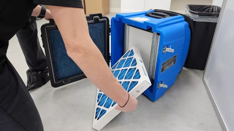
When discussing HEPA performance in the field, the starting point should always be the filter itself. A HEPA filter is a precision component made of densely packed microfibers arranged to create a complex path for air to travel through. When properly manufactured and installed, this media forces particles to interact with the fibers through diffusion, interception, and impaction. However, the filter can only perform as intended if it is in good condition and installed correctly within a sealed system.
One commonly overlooked issue in field use is improper filter installation. HEPA filters rely on tight sealing surfaces around the filter frame to prevent air bypass. If a filter is not fully seated, if the gasket is damaged, or if the filter frame is warped, air can leak around the edges rather than passing through the filter media. This type of leakage is known as breakthrough, and it can dramatically reduce filtration performance even when the filter media itself is functioning perfectly.
Another common issue involves physical damage to the filter media. HEPA filters are fragile. The fiberglass media can be punctured, torn, or crushed during installation, transport, or cleaning of the unit. Even small punctures can create direct pathways for contaminated air to pass through the filter. Because these defects may not be visible once the filter is installed, damaged filters can remain in service without the operator realizing performance has been compromised.
Looking for quick answers on restoration, remediation and cleaning topics?
Try Ask R&R, our new smart AI search tool.
Ask R&R →
Filter loading is another factor that directly affects performance. As particles accumulate within the filter media, airflow resistance increases. Over time this causes a drop in airflow through the unit and increases pressure across the filter. While some loading is normal and can even improve capture efficiency in certain size ranges, excessive loading will eventually restrict airflow to the point that the device can no longer move sufficient air through the environment, or force breakthrough. Air will always follow the path of least resistance.
This is why pleated prefilters are critical to HEPA system performance. Prefilters capture larger particles before they reach the HEPA stage, preventing premature loading of the final filter. When prefilters are ignored or replaced too infrequently, the HEPA filter becomes the primary collector of larger debris, dramatically shortening its useful lifespan. Most prefilters are MERV 8, filtering down to 1 micron.
Contractors should also remember that not all HEPA filters are identical. Differences in media density, pleat design, frame construction, and gasket quality can all affect durability and airflow resistance. Regardless of the design, the key requirement remains the same: the filter must maintain 99.97 percent efficiency at 0.3 microns when installed in the device.
Ultimately, the effectiveness of any HEPA system begins with the condition and integrity of the filter itself. If the filter is damaged, improperly installed, or excessively loaded, no amount of airflow management or equipment placement will compensate for the loss in filtration performance.
One misconception worth noting involves odor. Just because a HEPA unit’s exhaust has a strong smell does not mean the unit is not performing correctly. HEPA filters capture particulate matter, not odor molecules. If the air coming out smells musty or like smoke from a fire, it is likely residual odor molecules still present in the filter media, not the original contaminants themselves.
The Machine Around the Filter
A HEPA filter can only perform as well as the machine that surrounds it. Even if the filter media itself meets the required 99.97 percent efficiency at 0.3 microns, the housing, seals, and internal structure of the equipment must ensure that all air passing through the device is forced through the filter. If air can bypass the filter anywhere inside the unit, the system is no longer delivering HEPA-level performance. Be wary of HEPA units that advertise HEPA filter efficiency rather than HEPA-level performance.
One of the most critical components is the filter sealing system. Most HEPA filters rely on a gasket that compresses against the filter housing when installed, creating an airtight seal around the perimeter of the filter frame. If that gasket becomes worn, damaged, or unable to compress properly, contaminated air can leak around the edges of the filter instead of passing through the filter media. When gaskets can no longer seal effectively, one practical technique is to reinforce the seal with non-permeable tape, such as polyethylene plastic tape, around the filter frame. While this does not replace proper equipment maintenance, it can help restore an airtight seal in the field when needed.
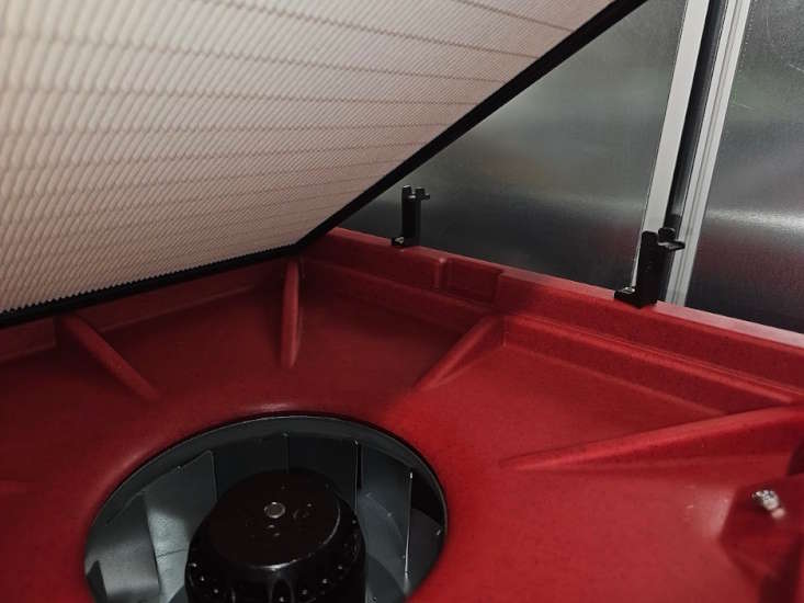
Gasket system: black strip on filter edges meets the plastic ridge to seal. Credit: Branden Adams, ARTI
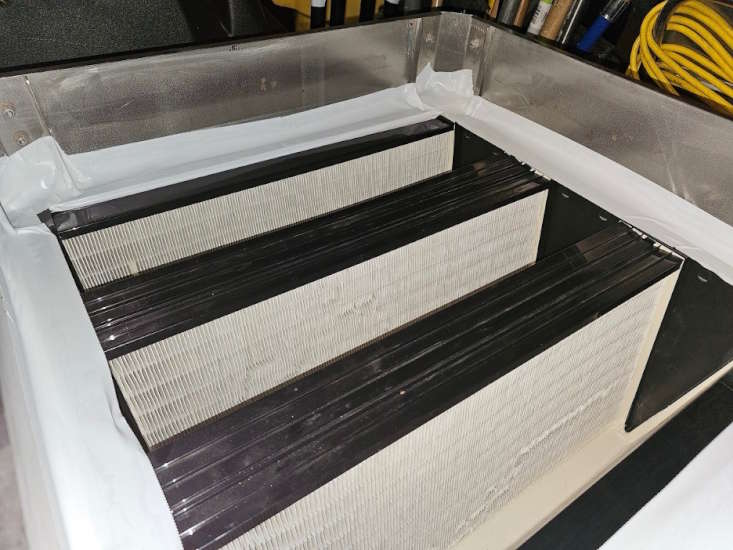
Non-permeable tape reinforcing gasket seal on edges of HEPA filter. Credit: Branden Adams, ARTI
The condition of the filter housing and internal structure is equally important. Warped filter racks, bent retaining brackets, or damaged frames can prevent the filter from seating correctly. Even small gaps between the filter frame and housing can allow significant air bypass. Equipment that has been dropped, transported frequently, or heavily used can develop these issues over time, often without the operator noticing.
Proper procedures during filter replacement and equipment removal are also important for preventing cross contamination. When removing an air filtration device from a containment area, it is good practice to cover the filter intake while the unit is still running. This allows the machine to continue pulling air through the HEPA filter while the intake is sealed, helping prevent contaminated air from escaping the device during shutdown or transport.
Prefilters should be changed while the unit is still operating whenever possible. With the unit running, airflow continues to move contaminants toward the filter rather than allowing dust and debris to fall back into the environment during removal. The HEPA filter itself should generally be replaced off the jobsite, where the process can be performed in a controlled environment without releasing contaminants back into the work area.
Special care should also be taken to protect the motor and internal components from contamination. If debris bypasses the prefilter stages and enters the motor housing, it can damage the equipment and potentially spread contaminants through the exhaust. Maintaining clean prefilters and ensuring proper installation helps prevent this type of internal cross contamination.
Finally, contractors should pay attention to signs that equipment requires servicing. Unusual motor noises, excessive vibration, or a unit that causes noticeable rumbling through the floor can indicate mechanical problems or worn components. Continuing to operate equipment in this condition can reduce filtration performance and lead to further damage. Don’t be like young me, who once used a fire extinguisher to weigh down the corner of an air filtration device (AFD) to prevent it from shaking the floor.
HEPA Deployment
Where HEPA air filtration devices are placed within a workspace has a direct impact on how effectively they capture airborne contaminants. Simply turning on a machine in the corner of a room does not guarantee that contaminated air will reach the filter. Proper deployment requires an understanding of how these devices actually capture particles from the surrounding environment.
For general air cleaning across a work area, AFDs should be positioned in strategic locations throughout the space rather than clustered in one area. Spreading units out helps airborne contaminants encounter a filtration device before settling on surfaces or migrating into adjacent areas. This approach is particularly useful in large projects where contaminants may be generated across multiple work zones.
During demolition or heavy disturbance activities, at least one AFD should be placed as close to the source of dust generation or contamination as reasonably and practically possible. This is especially important during mold remediation, where disturbing contaminated materials can release large quantities of spores and fragments into the air. Positioning the intake near the work area allows the device to capture contaminants before they disperse throughout the containment.
It is also important to avoid blocking the intake of the machine. AFD intakes placed directly against a wall or obstruction reduce the area from which the unit can draw air. These devices pull air from the surrounding environment in a pattern similar to a vacuum cleaner. Air is drawn toward the intake from the immediate area around it, often referred to as the capture zone. Contaminants located outside that capture zone may remain suspended in the room or settle onto surfaces before they ever reach the filtration device. If the capture zone is restricted by walls, equipment, or debris, the effectiveness of the device is greatly reduced. Like a trash bag getting sucked into the intake.
In some situations, air washing techniques can help move particles into this capture zone. Using controlled bursts of compressed or pressured air can dislodge particles from surfaces and direct them toward the intake of the AFD. When used carefully, this technique helps move contaminants from surfaces into the air where they can be captured by the filtration system.
Managing Airflow
In contaminated environments, airflow should be controlled and intentional. In most contaminated restoration scenarios, HEPA AFDs should be the only source of airflow within the workspace. Introducing uncontrolled air movement from fans or other sources can aerosolize and spread contaminants. This is especially true with mold, where a slight breeze can aerosolize millions of spores, let alone a 3000 CFM air mover.
There is one notable exception. In environments involving fentanyl or other powdered hazardous substances, airflow should be eliminated. Any air movement can disturb settled particles and increase the risk of exposure. In these situations, controlling contamination takes priority over any kind of air filtration.
A key concept in airflow management are pressure differentials. Establishing negative pressure within a containment ensures that air moves from clean areas into contaminated areas, rather than the reverse. This directional control helps prevent contaminants from escaping the work area and spreading to unaffected spaces. Positive pressure may be used in certain situations, such as in the creation of temporary clean rooms. However, in most remediation work, negative pressure is the standard approach.
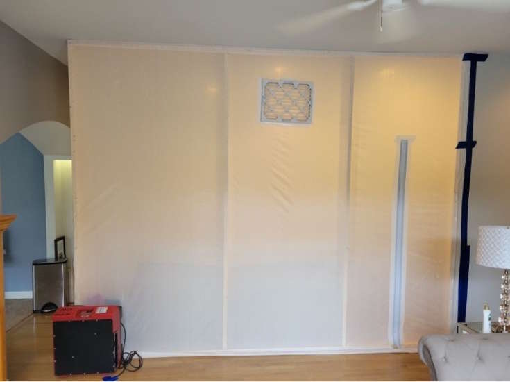
When using an AFD to create negative pressure, proper setup is critical. If a containment requires a makeup air opening or filtered intake, the intake and exhaust should be positioned on opposite sides of the containment, ideally in opposite corners. This creates a path for air to travel across the entire workspace, creating cross ventilation and reducing the likelihood of stagnant areas.
Air should always move from cleaner areas toward more contaminated areas. This cascading effect ensures that contaminants are continuously drawn away from cleaner zones and toward the filtration device. Negative air systems accomplish this by pulling clean air into the containment, passing it through the contaminated space, and exhausting it through the HEPA filter.
Additional techniques can be used to improve airflow distribution within the containment. One such method is the use of lay-flat ducting, or “air tails,” attached to the exhaust of an AFD. This allows filtered air to be directed to specific areas within the workspace, helping to move particles toward the intake and into the capture zone. When used correctly, this can improve overall effectiveness without introducing uncontrolled turbulence.
Airflow is often discussed in terms of air changes per hour (ACH). ACH represents how many times the total volume of air in a space is replaced in one hour. A common baseline for restoration work is 4 air changes per hour, although higher rates may be required depending on the level of contamination. For healthcare, please see ASHRAE’s 170 standard, Ventilation in Health Care Facilities, chart 7.1 for ACH requirements in every room type. Since we always know what ACH, we are trying to achieve is, we calculate the total CFM required to obtain that ACH.
CFM can be calculated using the following equation:
ACH × Room Volume (ft3) ÷ 60 = CFM
Once total CFM is obtained, divide that number by the reported CFM of the HEPA AFDs being used. Rounding up, that is how many HEPA AFDs to install to achieve that required ACH.
It is important to note that the rated CFM of an AFD is sometimes reported without filters installed. Once prefilters and HEPA filters are in place, actual airflow will be reduced. Contractors should verify this when sizing equipment and not rely solely on manufacturer specifications, unless the manufacturer specifies that the reported CFM is with filters.
Verification
No matter how well equipment is deployed or maintained, HEPA performance should never be assumed. Verification is the only way to confirm that a system is functioning as intended in real-world conditions. Two of the most useful tools for this are an anemometer and a particle counter.
An anemometer is used to measure airflow and verify actual CFM output from an air filtration device. Since manufacturer ratings can be based on ideal conditions without filters installed, actual airflow is typically lower. Not only that, but as a HEPA filter becomes more loaded, even though it can increase the amount of particles captured, it can reduce the amount of CFM the machine can achieve. Measuring airflow at the exhaust allows contractors to confirm that the unit is moving the expected volume of air and achieving the desired ACH within the space.
A particle counter provides a direct way to evaluate filtration performance. For HEPA verification, a 6-channel particle counter that includes a 0.3-micron channel is essential. Since HEPA filters are rated at 0.3 microns, this is the most meaningful data point when assessing performance.
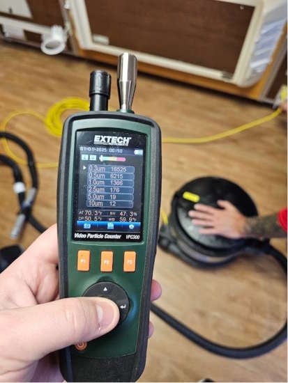
Very high particle count at 0.3µm from the exhaust of a HEPA vacuum. Ambient air counts averaged around 2400. Credit: Branden Adams, ARTI
To verify an AFD, particle counts should be compared between ambient air entering the unit and the air leaving the exhaust. In practice, this often means taking a reading at the intake and then at the exhaust. It is important that the airflow rate across the probe remains consistent for both measurements to ensure an accurate comparison. Multiple readings should be taken at each location and then averaged to reduce variability.
A properly functioning HEPA system should show a 99.97% reduction in particle counts at 0.3 microns when comparing intake to exhaust. This confirms that the filter and the machine are working together as a complete system. In practice, this often means that there should be 1 or less particles reported on the particle counter.
Verification becomes even more important when dealing with HEPA vacuums. Many vacuums are not post-HEPA filtered at the exhaust, which makes it difficult or impossible to confirm whether contaminants are being fully captured or reintroduced into the environment. Without a way to measure exhaust air, contractors are often relying on assumptions rather than data.
Additional Field Techniques
Beyond standard deployment and airflow control, there are several practical techniques for HEPA devices in the field that can improve functionality or provide temporary solutions when ideal equipment is not available.
In situations involving light contamination or smaller containment spaces, a HEPA vacuum can be used to create negative air in a pinch. While not a replacement for a dedicated AFD, a vacuum can help pull contaminated air through a HEPA filter when connected to a hose and positioned appropriately. This approach should be used with caution and only when proper AFDs are not available, as airflow volume is limited and not all vacuums are designed for continuous air movement.
Another technique involves the use of a HEPA filter box paired with an axial air mover. In this setup, the axial fan pulls air through a HEPA filter assembly, creating a simple but effective filtration unit. This can be useful in large spaces or when additional filtration capacity is needed. However, the effectiveness of this method depends heavily on proper sealing of the filter within the box to prevent breakthrough.
“Double scrubbing” is another method used to improve air cleaning efficiency. This involves running multiple AFDs in succession so that air passes through filtration more than once. Each pass further reduces particle concentration, which can be especially useful in heavily contaminated environments. If an AFD is experiencing breakthrough and not performing to the 99.97% standard as verified by a particle counter, using this technique can ensure that the proper HEPA efficiency is achieved.
Example of double scrubbing. One AFD is inside the containment, depositing air into the AFD on the outside. Also, an example of cross ventilation with the makeup air filter. Credit: Branden Adams, ARTI
Since HEPA filters do not capture gases or odors, carbon prefilters can be added to address odor issues. Activated carbon works through adsorption, binding odor molecules to its surface. When odors are present, pairing carbon filtration with HEPA filtration provides a more complete solution by addressing both particulates and gas-phase contaminants.
These techniques can be valuable tools when used appropriately to improve overall performance in the field.
Conclusion
HEPA filtration is one of the most relied upon tools in restoration, but its effectiveness in the field depends entirely on how it is used. The difference between a properly functioning HEPA system and one that is simply running comes down to attention to detail. The condition of the filter, the integrity of the machine, placement within the workspace, and control of airflow all play a role in determining whether contaminants are actually being captured.
In practice, many of the issues seen on jobsites are not caused by the limitations of HEPA technology, but by how the equipment is handled. Small oversights such as poor sealing, improper placement, neglected prefilters, or unverified performance can significantly reduce efficiency without being obvious. Over time, these habits become normalized, leading to a gap between what contractors believe their equipment is doing and what is actually happening.
Verification is what closes that gap. Measuring airflow, checking particle counts, and confirming performance at the exhaust replaces assumptions with data. This allows contractors to make informed decisions, adjust conditions in real time, and ensure that the equipment is doing what it was designed to do.
At the end of the day, HEPA filtration is not complicated, but it is precise. When the fundamentals are understood and applied consistently, the results are predictable and effective. When they are ignored, performance suffers regardless of how advanced the equipment may be. The goal is not just to run HEPA devices, but to use them correctly and verify that they are working.
Even though I have mentioned several HEPA techniques, it is by no means exhaustive. When problems present themselves, get creative! And you may just come up with your own technique that grows into an industry standard.
Looking for a reprint of this article?
From high-res PDFs to custom plaques, order your copy today!


