Diagnosing Multi-Level Construction-Defect Water Losses
How thorough containment, drying, and diagnostic strategies improve project outcomes for complex water losses
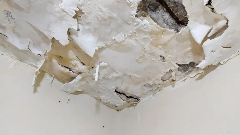
A homeowner in Melissa, Texas, noticed water staining on her garage ceiling. It was not a plumbing fixture she could see, not a roof leak she could trace, and not a spill anyone remembered. What the initial inspection revealed was a saturated section of ceiling drywall that measured roughly eight feet by seven feet, with a moisture reading of 528 against a dry standard of approximately 103.
The source was a bathroom supply line on the second floor. During the original construction, a nail was driven through the line. It held for years, slowly weakening under normal water pressure until the connection finally gave way. By the time the homeowner noticed something was wrong, water had traveled through the floor assembly, down the wall cavities, and into the garage ceiling below.
This kind of job, where the visible damage is nowhere near the actual point of failure, is one of the more difficult scenarios a restoration technician can walk into. The decisions made in the first hour of assessment will shape the entire project: whether the scope captures the full extent of moisture travel, whether containment protects unaffected areas, and whether the drying strategy accounts for every material in the path.
Start with the Diagnostic, Not the Equipment
When water crosses floor levels, the instinct is to start pulling equipment off the truck. But in a multi-level loss driven by a latent construction defect, the most important first step is mapping the moisture path before touching a single air mover.
The visible damage for this job was wet drywall on the garage ceiling which only accounted for part of the affected area. Thermal imaging revealed that water had tracked laterally through the second-floor subfloor assembly before finding vertical pathways into the garage ceiling cavity. Moisture mapping confirmed saturation in wall cavities, floor framing, and insulation that were not visible from either level.
This is where construction-defect losses differ from a standard overflow or appliance leak. In a typical supply line break, you expect the water to follow a relatively predictable gravity path: straight down through the nearest penetration. But when the failure has been slow or intermittent, sometimes over months or years before a full rupture, the water has time to wick into materials laterally. It saturates subfloor plywood, travels along joist bays, and migrates into adjacent wall assemblies well beyond where gravity alone would have carried it.
The practical takeaway: thermal and moisture readings should cover every adjacent assembly on both levels, not just the visibly damaged area. Readings taken at the perimeter of visible damage will almost always need to extend further. If the affected area on one level does not align directly above or below the affected area on the other level, lateral moisture travel is the likely explanation, and the scope needs to reflect that.
Looking for quick answers on restoration, remediation and cleaning topics?
Try Ask R&R, our new smart AI search tool.
Ask R&R →
Containment When Two Floors Share One Problem
Multi-level water losses create a containment challenge that single-floor jobs do not: the moisture path connects spaces with different materials, different ambient conditions, and different access points. Containment has to account for all of it.
For this particular project, the restoration team established containment on three fronts. First, sticky plastic was applied to the carpeted stairway connecting the two levels. Carpet on stairs is notoriously difficult to protect during a multi-day mitigation, and any foot traffic carrying moisture or debris between floors risks cross-contamination of unaffected areas. The sticky plastic served as both a moisture barrier and a dust barrier throughout the project.
Second, dust barriers were installed at the boundaries of the affected zones on both floors. This is standard practice under ANSI/IICRC’s S500, but it matters more in multi-level jobs because airflow patterns change when you are running drying equipment on two separate floors connected by open stairwells or HVAC ducts. Without proper barriers, air movers on one level can push moisture-laden air into unaffected spaces on the other.
Third, and this is the part of the job that required the most deliberate planning, the garage ceiling cavity was converted into a controlled drying chamber. The team sealed the cavity after removing the saturated ceiling drywall, essentially creating an enclosed space where temperature, airflow, and humidity could be managed independently from the rest of the structure.
That third containment decision, treating the garage ceiling cavity as its own drying environment, is one that is easy to overlook. In many jobs, the garage is treated as a secondary space. But when the ceiling cavity above is the terminal point for water that has traveled through two floors of building assemblies, that cavity is one of the most critical areas in the entire project. Leaving it open to the garage’s ambient air, which may be unconditioned, dusty, or fluctuating in temperature, and can slow the drying process significantly and introduce conditions favorable to microbial growth.
Equipment Strategy for a Split-Level Drying Job
Once diagnostic mapping is defined, the full scope and containment was in place, the equipment selection was driven by the specific conditions on each level rather than a one-size-fits-all approach.
On the second floor, the bathroom where the supply line failure originated, received an LGR dehumidifier paired with air movers. The space was smaller, the materials were limited to standard bathroom finishes and the subfloor assembly beneath them, and humidity levels could be managed effectively with a single dehumidifier in a contained area.
The garage presented a different set of conditions. Four air movers were deployed across the open area, aimed into the ceiling cavity. Layflat ducting was used to direct airflow into the sealed cavity space, ensuring that air movement reached the full depth of the joist bays and saturated framing rather than just cycling across the surface of the exposed structure. An air scrubber ran continuously in the sealed garage to maintain negative air pressure and filtered particulates from the demolition and drying process.
The rationale behind the different setups comes down to material type and cavity access. On the second floor, the affected materials were accessible and a relatively thin profile: tile backer, subfloor plywood, and standard framing. In the garage ceiling, the affected materials included thicker framing members, insulation batts, and the underside of the second-floor subfloor assembly, all contained within a cavity that had limited air exchange before the team opened it up. Layflat ducting in that cavity was essential because air movers positioned on the garage floor alone would not have generated enough velocity at the cavity level to drive evaporation from deep within the joist bays.
Monitoring, Adjustments, and Documentation That Closes the File
In any multi-level job, daily monitoring is not optional. It is the only way to know whether the drying plan is actually working, conditions have shifted, and any adjustments are needed.
The team logged moisture readings at consistent locations on both levels every day. The readings were compared against the dry standard established at the start of the project (approximately 103 for the materials in question). Equipment run times, humidity levels, temperature readings, and any adjustments to air mover positioning or dehumidifier settings were documented at each visit.
Two practical observations from the monitoring phase are worth noting. First, the garage ceiling cavity dried more slowly than the second-floor bathroom. This is expected given the mass of material in the cavity, the limited air exchange prior to intervention, and the fact that the garage is typically an unconditioned space. Technicians who monitored both levels and only compare them to each other, rather than to the dry standard, may prematurely pull equipment from the faster-drying area and leave the slower area underserved.
Second, documentation from construction-defect losses needs to be especially thorough because the cause of loss may become relevant to subrogation or builder liability discussions. Photographs and moisture logs from the initial assessment, daily monitoring, and final post-mitigation readings create a record that demonstrates the scope was appropriate, the timeline was reasonable, and the structure was returned to pre-loss moisture conditions. That documentation is what ultimately closes the file cleanly, whether the carrier, the builder, or a third-party engineer reviews it.
What Construction-Defect Losses Teach Us About Assumptions
Most technicians are trained to work from the visible damage inward. You see a wet ceiling; you look above it. You find a broken pipe, you contain the water, remove the affected materials, and dry the space. That workflow functions well for the majority of residential water losses.
Construction-defect losses break that workflow because the damage has developed in ways that do not follow the standard visible-to-hidden progression. The nail in the supply line was installed during construction. It did not fail because of age, freeze conditions, or misuse. It failed because of a defect that was concealed inside a finished wall for years. By the time it became a noticeable leak, moisture had already migrated through materials that a standard visual inspection would not have flagged.
For technicians walking into these jobs, the key lesson is this: when the visible damage does not align with a logical point of origin, slow down. Extend your diagnostic readings further than the visible boundary suggests. Build containment for conditions you have not confirmed yet, but suspect based on the moisture path. And document everything, because on these jobs, the technical record is often more important than the repair itself.
This project was straightforward once the full scope was defined, containment was in place, and the drying plan accounted for the specific conditions on each level. The complexity was front-loaded in the diagnostic phase. That is the nature of latent construction-defect water losses, and why the first hour of assessment, not the first piece of equipment, determines whether the project stays on track or becomes a dispute.
Looking for a reprint of this article?
From high-res PDFs to custom plaques, order your copy today!